|
|
Your source of photonics CAD tools | |
|
| ||
FIMMPROPA bi-directional optical propagation tool |
   |
Tapered Optical Fibers3D simulation with FIMMPROP softwareFIMMPROP is a very efficient tool for the modelling of optical fiber components, including fiber tapers. It can take advantage of the numerous fully vectorial fiber solvers available in FIMMWAVE and can model both:
We will show here how FIMMPROP can be used to model a tapered fiber used as a wavelength passband filter. FIMMPROP is a very efficient tool for the simulation of optical fiber tapers:
In this case we simulated light propagation in a fiber with an exponential profile, as can be generated by heating-pulling processes. You can see the profile below.
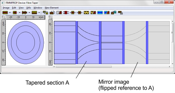
We used the FDM Fibre Solver, which relies on a finite-different method in cylindrical co-ordinates, to calculate the modes of the fiber. As the cylindrical symmetry applies to the entire structure, we were able to select only one azimuthal order for one polarisation, reducing considerably the number of modes that we needed to include in the simulation. In addition, FIMMPROP was able to take advantage of the mirror symmetry of the structure: as the second tapered section is the mirror image of the first taper section FIMMPROP was able to use the same data, allowing us to reduce the calculation time by almost 50%.
This combination of EME with the ability of taking advantage of the various symmetries of the structure make FIMMPROP extremely efficient: the scattering matrix for the structure was obtained in less than a minute, even though the structure has a length of a few millimeters for a wavelength of 1100nm. FIMMPROP allows you to vary parameters in order to optimise your design very efficiently. For instance, whilst the calculation of the taper itself takes less than a minute, scanning the length of the taper is a much faster process with a scan point obtained per second. This allowed us to plot the study the evolution of transmission with taper length, which is shown in the figure below. This reveals that an adiabatic taper with 98% transmission can be obtained for a total length of 3.5mm.
Note all the oscillations in the plot below: these are generated by the interference between the cladding modes in the centre of the device. These interferences could be taken advantage of to control the variation of the transmission with wavelength, e.g. making use of this tapered fiber as a wavelength filter. The wavelength dependency for a length of 1.55mm is shown below as an example.
The evolution of the intensity profile along the structure is plotted below for two different taper lengths of 10um and 2mm. In the first case, light is coupled to a large number of cladding modes, and we can see them interfering very clearly in the central section. The second case is adiabatic, most of the power remaining in the fundamental mode at all Z positions.
FIMMPROP can provide you with the evolution of the mode properties along the structure. This can be very useful to locate anti-crossings between modes and identify whether and where coupling between the different modes is likely to occur. The evolution of effective indices with Z for this structure is shown below near the centre of the structure; the anti-crossings between the different modes are pointed at by arrows.
|
 © 2023 Photon Design copyright all rights reserved |

 |