FIMMPROPA bi-directional optical propagation tool |
   |
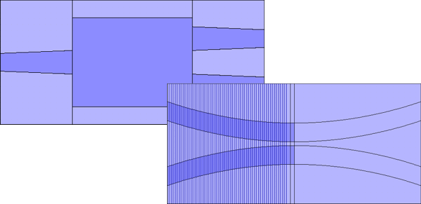
Taper ModellingModelling tapers and continuously varying structures with FIMMPROPFIMMPROP allows you to model propagation in z-varying sections, as can be commonly found in tapers, directional couplers, Y-junctions etc. This is done by discretising such sections along the axis of propagation and calculating the local modes along the taper. FIMMPROP can model tapers of arbitrary length and complexity more efficiently than most simulation tools and it can sweep design parameters very efficiently; for instance scanning the length of a tapered waveguide is quasi-instantaneous.
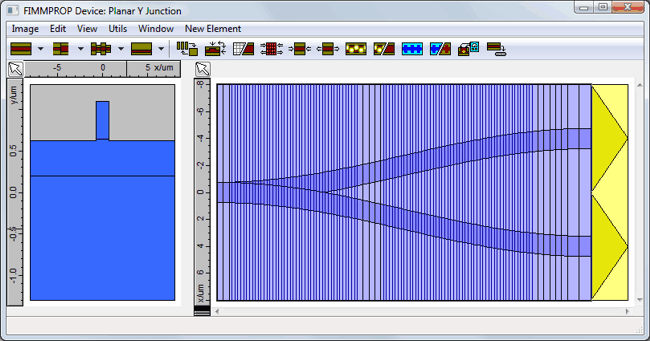
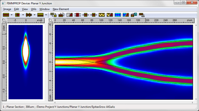
A unique adaptive taper algorithmFIMMPROP includes a unique adaptive taper algorithm, which can refine the discretisation dynamically depending on the variations of the eigenmodes. For instance in the planar Y-junction shown below, the discretisation needs to be much finer in the region where the waveguide widens than in other parts of the structure, where the width of the waveguide remains constant. Attempting to model this taper with a constant-step taper algorithm would be very inefficient, as to obtain the same accuracy you would need to apply the finest discretisation everywhere.
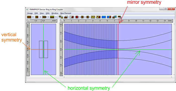
Photon Design has a well established expertise in the modelling of such structures, and pioneered the development of methods for the modelling of tapers and z-varying structures with EME by publishing articles on the subject as early as 2003 [1]. Taking advantage of symmetriesMany tapered structures include one or two planes of symmetry, and other structures like ring couplers or directional couplers include mirror symmetries. FIMMPROP can take advantage of such symmetries when modelling tapers, reducing calculation time by up to 16x compared with an algorithm that would not account for such symmetries.
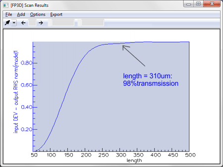
For tapered fibers, FIMMPROP can even take advantage of the cylindrical symmetry of the structure through the use of fiber solvers, making calculations extremely fast. Instantaneous taper length scansOnce the scattering matrix for the taper has been calculated, FIMMPROP is able to vary some parameters very quickly using the FIMMPROP Scanner or using scripts. In most cases varying the length of a taper can be done almost instantly. This allows you to optimise the length of the taper at a very low cost in calculation time. For instance in the Y-junction shown above, the initial calculation of the scattering matrix took 110s. Once this was calculated, the transmission versus length scan below only took 0.2 seconds per step.
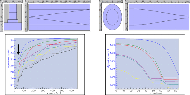
Benefits of modal analysisFIMMPROP can help you understand the physics of your taper in more detail than any other tool:
Case studiesYou can find below a few examples of applications taking advantage of FIMMPROP's taper algorithm. Planar geometry: Optimize Taper Designs (with Kallistos) Optimize S-Bends (with Kallistos) Fibre geometry: Tapered Metal-coated SNOM Fibre Probe Reference[1] D. F. G. Gallagher, T. P. Felici, "Eigenmode expansion methods for simulation of optical propagation in photonics: pros and cons", Proc. SPIE 4987, Integrated Optics: Devices, Materials, and Technologies VII, 69 (2003) - PDF
|

