FIMMPROPA bi-directional optical propagation tool |
   |
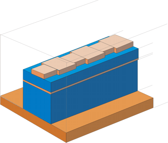
Optical Grating Mode-Size Converter3D optical grating simulation with FIMMPROP softwareFIMMPROP was used to model an optical grating in 3D: a periodic directional coupler designed as a mode-size (spot-size) converter. The aim of the device is to optimise the coupling from an input waveguide, in which the power is confined to a thin guiding layer, to a SMF-28 fibre (fiber to chip coupler). This is done by propagating the input beam through in a periodic structure, in which it is progressively coupled to a broader mode. DesignThe structure consists of two buried waveguides – a thin wide one buried deep in the structure and a thicker narrower one above that has a periodically varying width. This grating causes resonant coupling between the two supermodes of the structure if the grating period is designed correctly. The structure is simulated at a wavelength of 1.55µm. It is schematically drawn below, with the two guiding regions shown in orange.
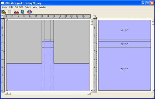
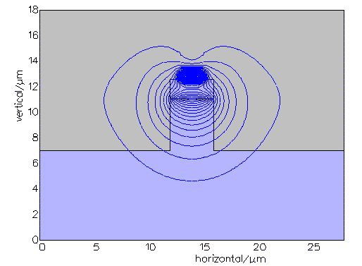
The waveguide cross-section of one of the half-periods is shown below. The second half-period corresponds to the same cross-section with a slightly wider top ridge. You can distinguish the two guiding regions on the cross-section.
Modelling gratings with FIMMPROPFIMMPROP can model this structure using two different rigorous methods: either EigenMode Expansion (EME) or its Rigorous Coupled Mode Theory engine (RCMT). In this case we used EME for the simulations as it allows us to use the semi-analytical FMM Solver, which will allow us to resolve the very thin layers very efficiently. Preliminary AnalysisThis is in many ways a challenging problem
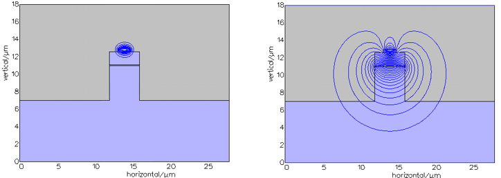
to model: None of these issues are a problem for FIMMPROP. FIMMPROP being a frequency domain tool, it can deal easily with long devices. More to the point, it will take advantage of the periodicity of the structure thanks to its scattering matrix approach. In total, no more than four different sets of modes will be required to simulate the device. Once the scattering matrix period has been calculated, FIMMPROP only needs to multiply this matrix by itself to obtain the response of the full periodic structure. The FMM Solver will be used to calculate the modes of the structure. The FMM Solver can easily resolve extremely thin layers. Indeed, it relies on semi-analytical techniques and does not need to discretise the cross-section. SimulationThe two supermodes between which the coupling occurs are shown below.
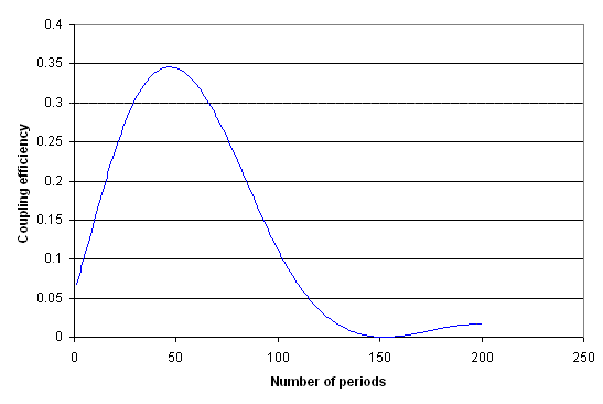
The device was simulated with FIMMPROP in 2 minutes 30s with an Intel Pentium 4 CPU at 3GHz. The number of periods included in the grating was scanned to optimise the coupling efficiency between the two supermodes. Scanning the number of periods in FIMMPROP is extremely fast thanks to the scattering matrix structure of the results, and the 200-point scanner was performed almost instantaneously. An optimum was found at 47 periods.
The output of the device after 47 periods is shown below. The FWHM of the beam (Ex-field) is 4.22um by 2.44um, whilst the input beam had a FWHM of 1.45um by 0.65um.
The transmission to an SMF-28 fibre was increased from 8.1% to 29.1% after introduction of the grating. These two transmission values were obtained after a fast optimisation of the respective vertical positions of the output waveguide and the optical fibre, performed with a scanner.
|

