|
|
Your source of photonics CAD tools | |
|
| ||
OmniSimOmni-directional photonic simulations |
    |
Nano-antennaeFETD and FDTD plasmonic simulations with OmniSim softwareWe will show here how OmniSim can be used to model various geometries of nano-antennae, including a bow tie antenna and a gold nut antenna. OmniSim offers many ways to model plasmonic structures, including:
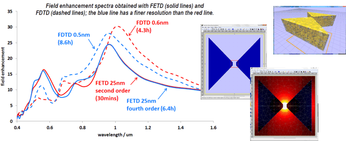
Having a number of different methods is very useful as it allows you to choose the most efficient method for your specific design, and also to run the calculation with multiple methods to check the accuracy of your calculations. In both these examples the FETD engine allows us to obtain highly accurate results much more quickly than the FDTD engine. Modelling a bow tie antenna with FETD Modelling a bow tie antenna with FETDModelling an inclined metal surface in 3D can be a major challenge for FDTD, as extremely small grids are required to obtain accurate results. In this example we measured electric field enhancement in the hole of a bow-tie antenna. The FDTD simulation still had not converged after an 8h30 simulation on a i7-860 CPU (4 cores) and was unable to locate the resonant wavelength and the amplitude of the resonant peak with precision. On the same computer the FETD algorithm converged with a calculation time of only 30 minutes! Such efficiency is made possible by the use of higher order elements in the finite-element mesh and by the FETD’s ability to avoid staircasing at the metal surface.
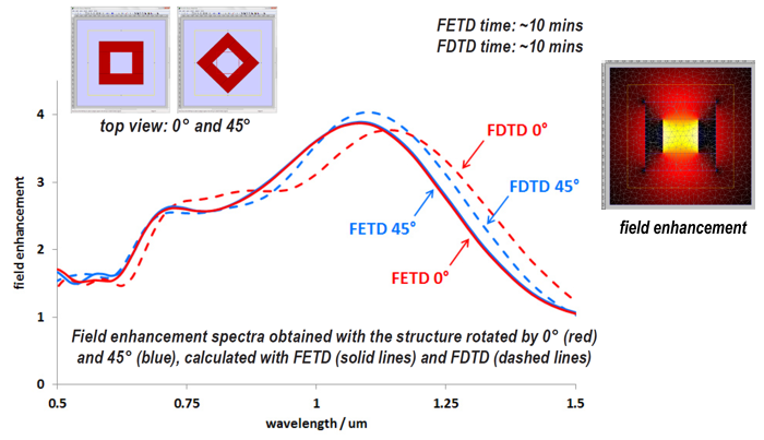
Modelling a gold nut with FETDThanks to its adaptive mesh, the FETD engine is much less orientation-sensitive than FDTD. This allows it to deal with slanted or curved interfaces with no staircase approximation and no material averaging at the surface. We simulated a gold nut structure with two different orientations and calculated the field enhancement in the centre of the hole. The FDTD engine displays erroneous discrepancies between the two orientations, caused by the staircase approximation of the diagonal interface at that resolution. For the same calculation time, the FETD engine gives almost identical results for both orientations for the entire spectrum.
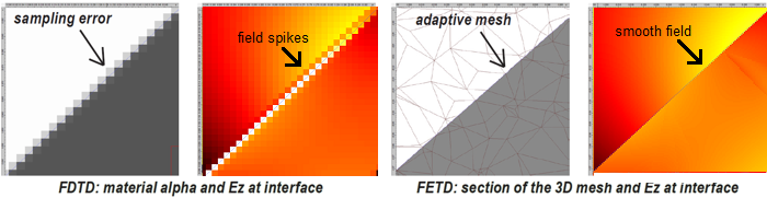
You can see below some of the effects of the staircasing in the rotated structure. The FDTD grid and field are shown on the left-hand side; note the spikes! On the right-hand side you can see a section of the adaptive FETD mesh and the corresponding field, without unwanted spikes this time.
|
 © 2023 Photon Design copyright all rights reserved |

 |