|
|
Your source of photonics CAD tools | |
|
| ||
HaroldA hetero-structure laser diode model |
    |
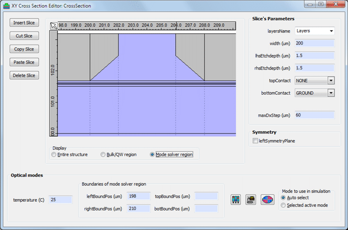
XY Laser ModuleHarold’s XY Laser Module extends Harold’s algorithm so that the lateral structure of laser devices is accounted for. It uses the same physical model as a Harold 1d simulation but solves the electrical/optical/thermal problem on a 2D (XY) grid, the starting point being a 2D cross-section, rather than a single 1D epilayer stack. Harold’s XY supports insulating layers, graded etching, and allows n and p-contacts to both be on the top of the structure. Its non-uniform simulation grid allows rigorous and efficient simulation of lateral current and heat spreading in the region below and either side of the active region/optical mode, which may extend for 100s of microns. In addition, it can simulate multimode operation and can simulate the change in the optical mode properties with increasing bias (hot-cavity effects). All this makes it ideal for the detailed modelling of a variety of laser designs, from simple ridge waveguide lasers to SOI hybrid lasers, high-power lasers with asymmetric waveguides and p-n blocking buried het lasers. The XY Laser Module uses the Harold’s existing layers editor, trap definition editor and mesh policy editor, making it easy to adapt and use existing Harold projects to set up XY simulations. The XY Laser Module also has the same execution modes as a Harold 1D simulation: Test mode (for quick diagnostics), Isothermal (pulsed), and Self-Heating (CW) modes. Cross-section editorThe XY Laser Module’s cross-section editor allows you to fully define a laser’s 2D cross-section. A cross-section is composed of a number of vertical slices, of varying widths, each of which uses its own (or a shared) epitaxial layer structure. Slices can be etched to varying depths and can also have graded etching. Each slice can have its top or bottom connected to the bias contact, the ground contact, or no contact at all. The cross-section editor incorporates our powerful FDM Mode Solver which allows for detailed mode analysis including our Farfield Calculator.
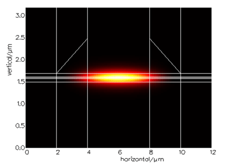
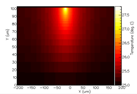
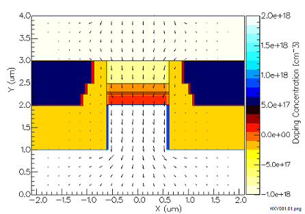
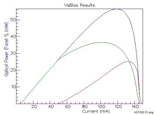
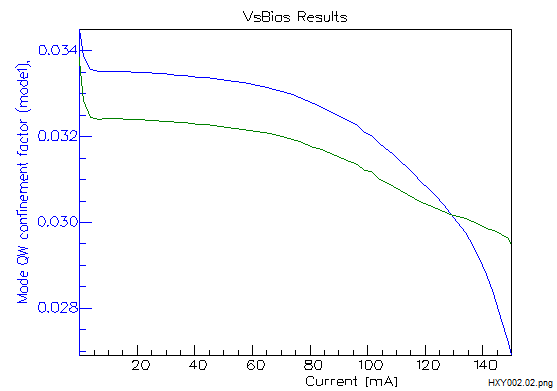
Simulations resultsIn addition to Per Bias results (i.e. vs. bias current/voltage/current density), Harold XY produces 2D lateral-vertical profiles of various quantities, including:
Comparison with PICWave, Harold and Harold EAMPlease see here for a comparison of the active component (laser diode, SOA, modulators etc.) modelling capabilities of PICWave, Harold, Harold XY and Harold QCSE.
|
 © 2023 Photon Design copyright all rights reserved |

 |