|
|
Your source of photonics CAD tools | |
|
| ||
FIMMPROPA bi-directional optical propagation tool |
   |
Design InterfaceCreate a large variety of photonic components effortlessly!FIMMPROP offers both great control and high flexibility to design 2D and 3D structures, for planar geometries, cylindrical geometries (optical fibers) and arbitrary sections, whether it is to model simple structures such as MMIs, or more elaborate ones such as tapers, Y-junctions, bends or couplers of all kinds. A large variety of design tools are provided to allow efficient design and support fast and accurate simulations, thanks to the optimisation of the algorithms associated with each type of element. Straight waveguides Straight waveguidesFIMMPROP can model straight sections extremely easily. Once the modes are calculated, the propagation is instantaneous, even along a km! Straight sections can be designed using one of FIMMWAVE's waveguide editors, or using the Planar Section tool.
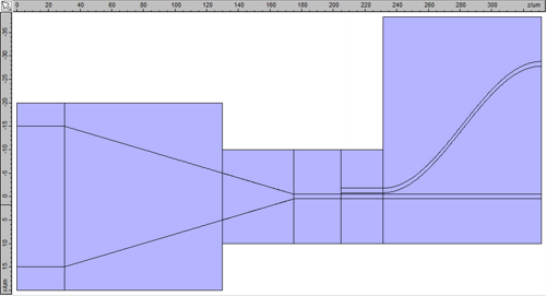
Another example is shown is with an MMI Coupler, composed of a succession of straight sections.
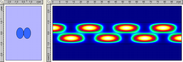
Periodic structuresFIMMPROP also allows you to design periodic sections in an automated way. All you need to do is define the period and tell FIMMPROP how many of periods to calculate. Thanks to its scattering matrix approach, FIMMPROP only needs to simulate the period once. The rest of the calculation is quasi-instantaneous, regardless of how many periods you are using: FIMMPROP only needs to multiply the scattering matrix of the period by itself!
In FIMMPROP, the time it takes to calculate propagation along a periodic structure with N period is of the order of log(N). With FDTD or BPM, the calculation time would be proportional to N, which is much less efficient! Similar gains in efficiency can also be made for non-periodic structures in which a given section is being repeated. Bent waveguidesFIMMPROP can easily model a bent waveguide-section in which the waveguide is bent horizontally or vertically with a variable curvature. The bend can be defined as a constant, expression or Euler curve. Bent waveguides can be modelled in a similar way to periodic structures, by decomposing them into a succession of short straight waveguides connected with a small tilt. Such structures can be very conveniently modelled in FIMMPROP.
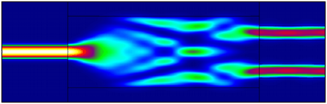
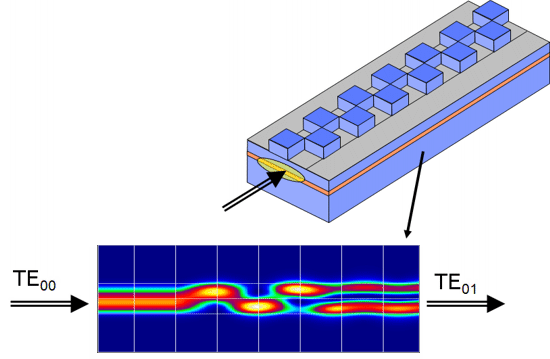
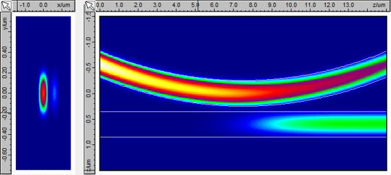
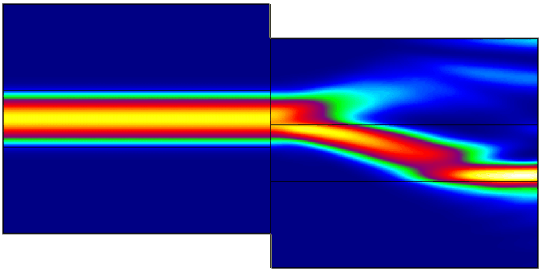
Tapers and smoothly varying structuresFIMMPROP is a very powerful tool to design and simulate continuously varying structures such as tapers, Y-junctions, vertical couplers, ring resonators, lensed waveguides etc. It is possible to create any smoothly z-varying structure with the FIMMPROP interface, and all the parameters in your structure can vary arbitrarily and independently with the direction of propagation. For instance in the example shown below, the width of the second layer varies as a piecewise linear function of Z whilst the position of the top ridges varies as an S-function and the height of the ridges decreases decreases linearly. You can parameterise any dimension, position or optical property in a fully arbitrary way, even using formulae or tabulated data.
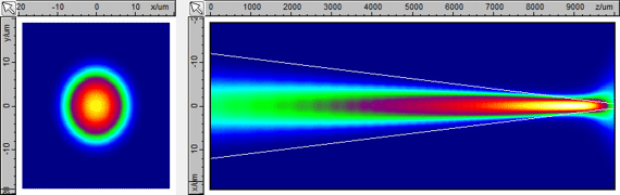
Tapered fibres can be easily designed; an example is shown below.
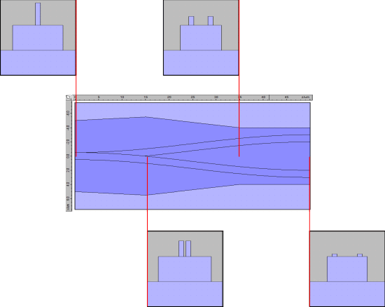
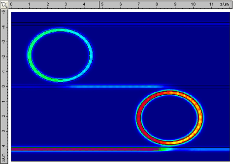
Designing FIMMPROP Planar Section was used to design the coupling region between ring resonator and a straight bus waveguide, shown below.
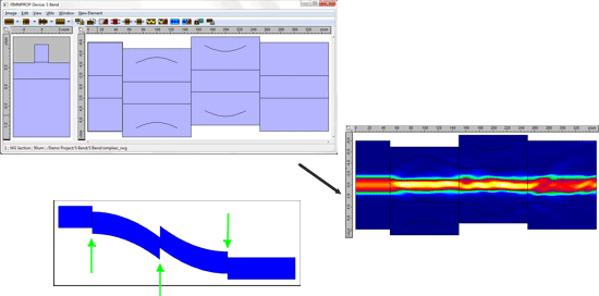
Varying computational domain size, introducing tilts and offsetsWith FIMMPROP it is possible to vary the size of the computational domain along the direction of propagation in order to improve calculation efficiency. You can see an example below, where the size and alignment of the different sections are optimised individually.
It is also possible to introduce tilts and offsets between various sections.
Thin film filters and AR coatings, propagation across free spaceEigenmode expansion is a powerful tool, but in uniform sections it is no match in speed for a fully analytical plane wave expansion. FIMMPROP allows you to use such analytical methods whenever possible, for instance to model propagation in a free space gap or to rigorously calculate the transmissions and reflections associated with thin film filters and AR coatings, or calculate farfield profiles. Flexible Layout for 2D structuresThe FIMMPROP Layout permits to design very complex 1D+Z structures with a great flexibility. The resolution of 1D+Z structures in FIMMPROP is fully analytical, and hence extremely fast and accurate.
|
 © 2023 Photon Design copyright all rights reserved |

 |