PICWaveA photonic IC, laser diode and SOA simulator |
    |
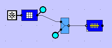
Dispersion-Compensating Fiber Bragg GratingSimulation with PICWave softwarePICWave is able to model Bragg gratings with near-arbitrary chirp and apodisation profiles. This example shows a chirped fiber Bragg grating (FBG) used for dispersion compensation, and the beneficial effect of apodisation. The circuit setup is shown below. On the left, a 10 Gbit/s input data signal is injected into a filter which models the dispersive properties of a fibre with a dispersion of ~1310 ps/nm (approx. 77 km of 17 ps/(nm.km) fibre). The dispersed signal is then passed through a 3-port optical circulator, whose second port is attached to a chirped grating which recompresses the signal, thus compensating for the fibre dispersion. The grating is 100mm long, with a linear chirp (bandwidth 0.8nm). The output signal then emerges from the third port, where it is measured.
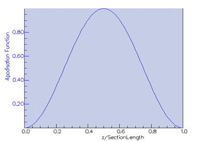
Two cases are simulated: a) Unapodised grating b) Grating apodised with raised cosine (cos2) profile shown below.
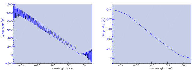
Group delay spectra for the grating reflection (i.e. time for reflected light to re-emerge) are shown below for the unapodised and apodised cases, respectively. It can be seen how apodisation removes the group delay ripple – this will improve the quality of the dispersion compensation.
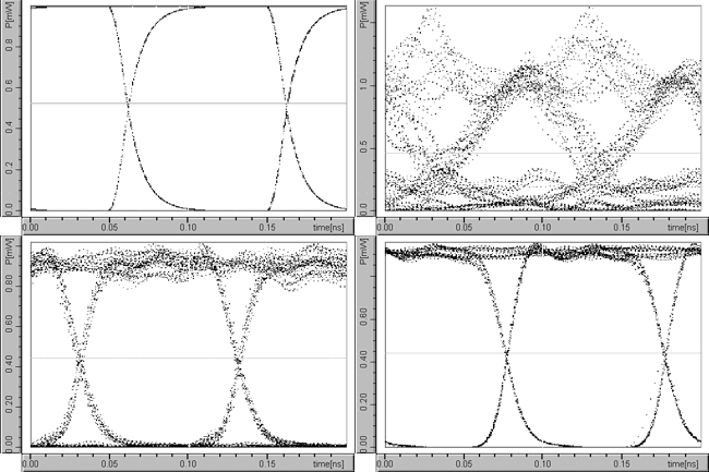
The figure below shows the simulation results viewed in PICWave’s oscilloscope. The strong distortion of the signal by the fibre dispersion can be seen clearly, as can the recovery of the original signal after dispersion compensation. Furthermore it can be seen how the dispersion compensation is improved through the use of apodisation.
|


