|
|
Your source of photonics CAD tools | |
|
| ||
PICWaveA photonic IC, laser diode and SOA simulator |
    |
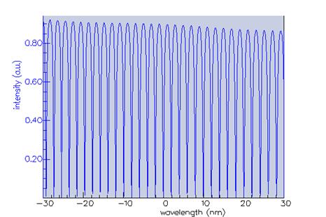
Large optical ring resonatorsSimulation with PICWave software based on a FIMMPROP component modelPICWave can easily and efficiently model ring resonators of 100's um diameter. The algorithm is many orders of magnitude more efficient than e.g. FDTD for this application, computing a triple 200um diameter ring resonator down to a wavelength resolution of 50MHz and spectral range of 50nm in just a couple of minutes. The result shown in the picture below shows a case of a 60um diameter ring resonator; PICWave yielded a result in a few seconds, while OmniSim-FDTD needed 14 hours.
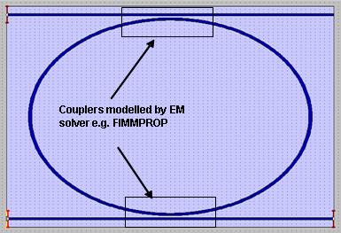
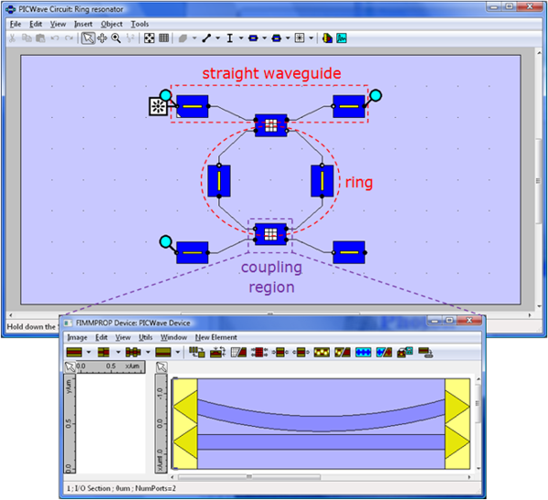
The difference is even bigger for larger ring resonators. The reason is that PICWave can use a large time step, and so can handle simulation durations in the range of several ns, yielding spectral resolutions finer than 1GHz. In fact, MHz resolutions are attainable. This kind of resolutions is important in the case of large ring resonators. Even the accuracy obtained is better. As you can see from the graph, PICWave agreement with the theoretical solution is remarkable, and calculated in a few seconds. Modelling with FIMMPROPIn this example we demonstrate how the FIMMPROP-PICWave link can be used when modelling a ring-resonator in PICWave. As illustrated below, the structure can be divided into the parts than can be modelled using built-in PICWave circuit elements – the ring (assuming no losses) and straight waveguides; and those which require detailed modelling with an EM solver i.e. FIMMPROP: the coupling regions.
The majority of ring resonator circuit is therefore constructed from built-in PICWave elements, apart from the coupling regions which are modelled using FIR sections. Via the PICWave-FIMMPROP link interface, the FIR sections can store FIMMPROP models of the coupling regions internally, and their scattering matrix spectra (coupling vs. wavelength) can be computed automatically via a TCP/IP connection with FIMMPROP.
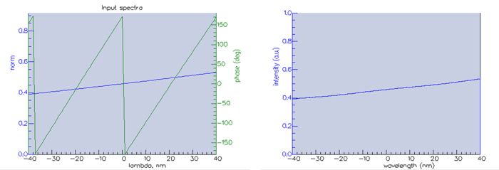
The FIR sections use the imported spectrum to generate an equivalent time-domain filter, which gives the time-domain response of the coupling regions. The figure below displays the imported scattering matrix spectrum and the corresponding FIR filter frequency-domain response, showing close agreement between the two.
The circuit was then simulated in the time-domain, and optical impulse signal with a flat spectrum was injected into the ring resonator and the response was measured. The effects of the modelled wavelength response of the coupling regions can be seen in the spectral results yielded by a time-domain simulation of the ring resonator.
|
 © 2023 Photon Design copyright all rights reserved |

 |