FIMMWAVEA powerful waveguide mode solver |
    |
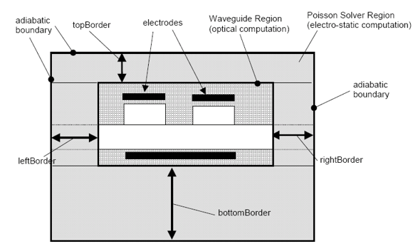
Electro-Optic SolverSimulating electro-optic effects in waveguidesThis solver is designed to model the electro-optic effects in a FIMMWAVE waveguide. Typically two or more metallic contacts are placed on or in the waveguide and a voltage applied to each. The module will determine the electric field distribution through the device and then generate a refractive index profile, taking into account the linear electro-optic effect (Pockels effect). The algorithm takes full account of a varying material permittivity. Both the permittivity profile and the contact arrangements can be of virtually any geometry. The modes of the waveguide with the applied voltage can be solved with any of FIMMWAVE's mode solvers may be used to calculate the waveguide modes. If the electro-optic effect results in anisotropy, you will be able to model it using the FDM and FEM Solvers which support an arbitrary diagonal permittivity tensor. Future versions should allow you to take advantage of the full permittivity tensor capability of the FEM Solver. Input SpecificationThe user may specify one or more contacts, each contact is assumed to be horizontal, but can be on top of or buried within the waveguide. The contact is an equipotential, with the voltage defined by the user. The Module uses the Material Database to determine the zero-field. The figure below illustrates some of the features of the model.
Output Results
CalculationThe calculation is based on a 2D Poisson solver, to determine the electrostatic potential profile in the two transverse directions (X/Y). The algorithm takes into account a spatially varying permittivity and also electro-optic coefficient. The algorithm uses a rectangular grid but the grid spacing is varied so that for example thin layers are discretised precisely. Materials are assigned a frequency dependent refractive index for DC to microwave range, independent of the optical index. The Poisson Equation Solver uses an anisotropic dc refractive index tensor with two non-zero coefficients: nedc,xx, nedc,yy. Design Curve GeneratorThe Generator will calculate the variation of the estimated change in mode effective index as the dimensions and voltages on the contacts are varied. Electro-Optic Module with FIMMPROP: Electro-Optic Switch DesignIf you also have FIMMPROP, the Electro-Optic Module will allow you to model the propagation in a electro-optic switch – typically a Y junction with electrodes placed to induce the light to travel preferably on one branch or the other. The Module and FIMMPROP will work closely together to permit one to study the effects of the electro-optic effect on the optical propagation.
|


