A 1x2 M.M.I. (Multimode Interference Coupler)
with Butterfly
Geometry
OmniSim 2D FDTD simulation
OmniSim can be used to model and simulate the
propagation of light through a 1x2 MMI. In this example, we use
OmniSim’s FDTD engine to calculate the transmissions and reflections of
an 1x2 MMI with butterfly geometry at different phase differences, and
compare its results to a paper published by A.J. Millan-Mejia et al.
[1].
Design of the structure
The 2D structure of an MMI with butterfly geometry is represented below.
Instead of allowing parasitic reflections to disrupt the functionality of the MMI,
butterfly geometry allows the unwanted light to escape. Optimized angles ensure that
the unnecessary light is redirected away from the main propagation path and out of the MMI.
Moreover, the implementation of butterfly geometry in MMIs was originally proposed by E. Kleijin [2].
In this example, the waveguide (background) has a refractive index of 2.729,
while the etched areas (blue) have a refractive index of 1.00. This structure is parameterized using variables
that can easily be changed in the OmniSim software.
The structure below is an approximate sketch of the butterfly geometry MMI on OmniSim.
In this particular graphic, the etched areas are in red, and have a refractive index of 1.00.
Using Kallistos, the parameters of the structure can be optimized
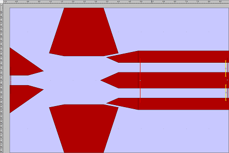
1x2 MMI with butterfly geometry on Omnisim, not optimized (Transmission 91.42%, Reflection 3.19%)
Optimization of parameters using Kallistos
The critical parameters are optimized using Photon Design’s Kallistos tool which is an automatic optimization tool that
can be used to find both local and global extrema.
The Kallistos user can easily re-optimize the MMI as (s)he sees fit, choosing the variables (s)he wishes to vary and
adding upper and lower bounds that are within the proper dimensions of geometry.
Here we wish to optimize two quantities: maximise transmission and minimise reflection.
The structure below is a 1x2 MMI with butterfly geometry that has been optimized by Kallistos.
Notice that the wedges on the right have drastically decreased in length, and have almost become triangular.
Also notice that the polygons on the left have become smaller, perhaps allowing more light to escape the device
in order to minimize reflection.
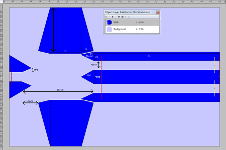
A labelled diagram of the 1x2 MMI with butterfly geometry on OmniSim,
optimized (Transmission 91.70%, Reflection 0.0879%)
The following graphic shows the propagation of light through the optimized MMI. Notice how part of the pulse
is able to escape the MMI and disperse elsewhere without negatively affecting the functionality of the MMI.
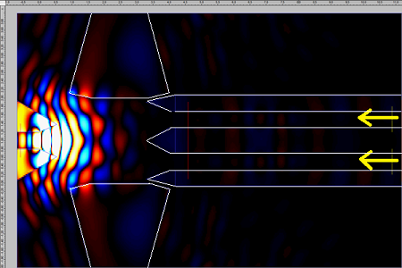
OmniSim FDTD simulation of Butterfly 1x2 MMI – two partly out-of-phase optical pulses are injected from right.
Light of incorrect phase can be seen directed out of the MMI and away from the main propagation path
Comparing results of OmniSim calculations with the results of Millan-Mejia et al.
The following graphic is a graph of the unoptimized MMI on Omnisim. This has a rather high,
undesireable reflections of ~3%.
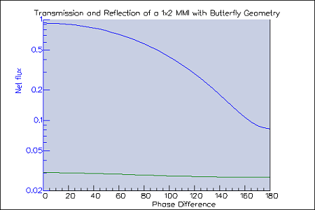
Effect of phase difference on the transmission (blue) and reflection (green) of a 1x2 MMI with butterfly geometry in OmniSim,
produced using OmniSim’s Scanner Tool (unoptimized)
The following graphic is a graph of the optimized MMI on Omnisim, which indicates both transmission and reflection
based on the phase difference of the light source, ranging from 0° to 180°.
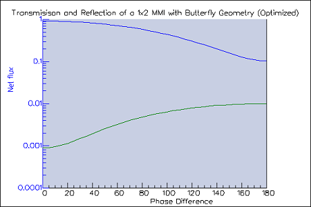
Effect of phase difference on the transmission (blue) and reflection (green) of a 1x2 MMI with butterfly geometry in OmniSim, produced using OmniSim’s Scanner Tool (optimized)
The next graph details the results from A.J. Millan-Mejia et al.
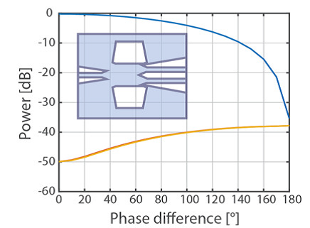
Effect of phase difference on the transmission (blue) and reflection (orange) of a 1x2 MMI with butterfly geometry [1]
Displaying the Kallistos’s optimisation map (see figure), you can readily see the areas that would yield the best transmission or
reflection values. Many other optimisers will give you just one “optimum” design. However Kallistos’s design will give you
also the 2nd, 3rd etc best designs too – this is important because sometimes the “best” design may be bad for other reasons,
e.g. difficult to manufacture.
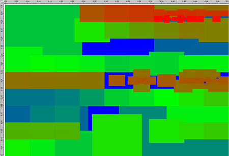
Kallistos Optimisation Map of the MMI (the more red the point is, the better its value).
This map shows variations against 2 design parameters but the optimisation varied other parameters too
for which additional maps are available.
Both the results from Millan-Mejia et al. [1] and from Omnisim indicate a positive correlation between the reflections
of the MMI and the phase difference of the light source. Moreover, both the transmission and reflection of each graph
exhibits similar trends, with transmission decreasing and reflection increasing when the phase difference increases.
The OmniSim MMI reflection results are a little different since Kallistos was told to focus on focused on minimising out of
phase transmission rather than minimising out of phase reflection. This can be easily remedied by altering the Objective
Function given to the Kallistos Optimizer.
Reference
[1] A.J. Millan-Mejia et al., 1x2 Multimode interference coupler with ultra-low reflections
in membrane photonic integrated circuits, 19th European Conference on Integrated Optics Proceedings
[2] E. Kleijin et al., Multimode interference couplers with reduced parasitic reflections, IEEE PTL, Vol. 26, No. 4.
|