|
|
Your source of photonics CAD tools | |
|
| ||
FIMMPROPA bi-directional optical propagation tool |
   |
Modelling a passive optical cavity (VCSEL, DFB)3D simulations with FIMMPROP softwareFIMMPROP can be used to model the passive modes of an optical cavity; it is particularly efficient to model cavities of VCSEL (vertical cavity surface-emitting laser) or DFB (distributed feedback) lasers. FIMMPROP can model such devices very efficiently and accurately:
Modelling optical cavities with EMEThe cavity mode is given by the eigenmode of the scattering matrix (Rl*Rr) describing the propagation through one loop of the cavity, where Rl, Rr are the reflection matrices of the left and right halves of the cavity. Tools are provided with FIMMPROP to find the eigenvalues and eigenvectors of (Rl*Rr). Geometry of the designFor this example we considered a cavity based on a cylindrical symmetry waveguide, which could be the underlying structure for a VCSEL or a DFB laser. We considered two designs:
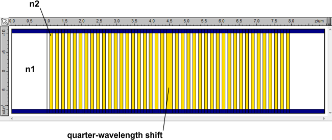
The geometry of the quarter-wavelength shifted grating is shown schematically below; you can see that the high-index half-period (shown in yellow) in the centre of the cavity is twice the length of the high-index half-periods in the gratings either side. In the fully periodic design, the central period is identical to the rest of the grating.
The design parameters are summarised in the table below.
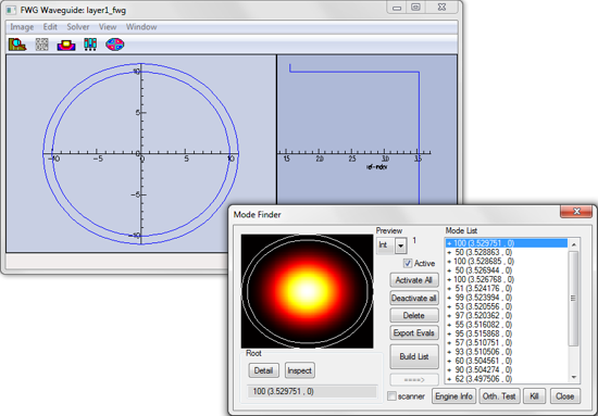
FIMMPROP can be used to find cavity modes based on either a single 2D mode of the cross-section, or on a combination of modes. In this case we solved the eigenproblem for the fundamental mode in the VCSEL (this would be the HE11 mode in a fibre-based DFB laser cavity). This mode is shown below for the high-index waveguide.
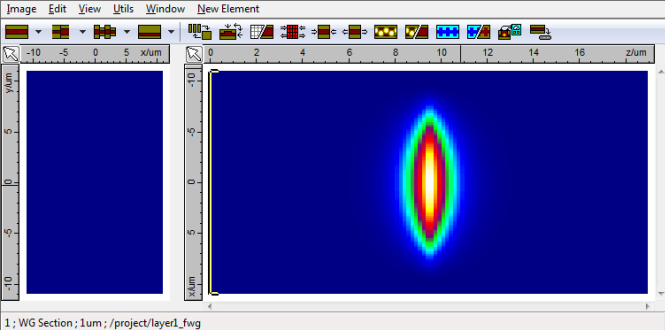
Simulation resultsThe final cavity mode profile can be seen below. The Cavity Mode Calculator is able to launch the light into the middle of the cavity. The Calculator finds many modes across the given wavelength spectrum and the peak efficiency is found close to 1.1µm.
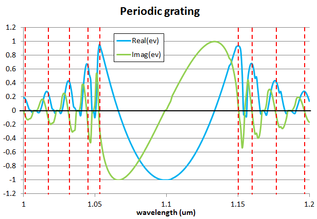
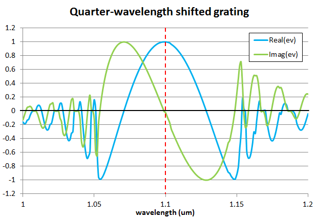
The cavity mode is shown above. It is efficiently confined within the cavity. You can find below a plot of the real part (blue) and imaginary part (green) of the eigenvalue of the solution of the round-trip scattering matrix for the fundamental mode. The resonances are shown in red lines. They correspond to wavelengths for which the imaginary part of the eigenvalue is zero and the real part of the eigenvalue is positive, which means that the beam is in phase with itself after a round trip. This first plot shows the resonances for the periodic grating; there are multiple resonances away from the Bragg wavelength, with significant round-trip losses ranging from 9.4% to 96.4%.
This second plot shows the same data for the quarter-wavelength shifted grating. Here you can see a single resonance at the Bragg wavelength, with a much lower round-trip loss of 0.02%.
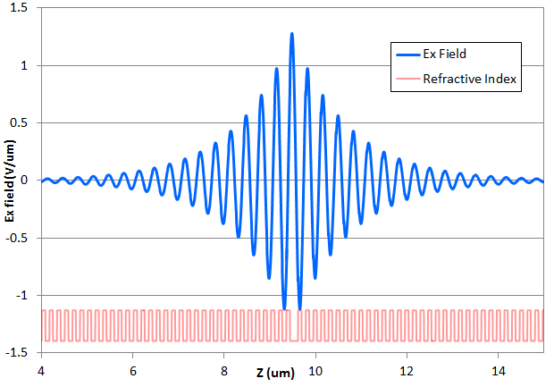
You can see below the Ex field profile of the cavity mode plotted versus Z and measured in the centre of the fibre. This plot was measured at resonance for the quarter-wavelength shifted design. The variations in refractive index of the grating are shown underneath in red.
|
 © 2023 Photon Design copyright all rights reserved |

 |