|
|
Your source of photonics CAD tools | |
|
| ||
PICWaveA photonic IC, laser diode and SOA simulator |
    |
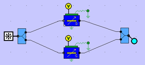
A Travelling Wave ModulatorSimulation of a travelling-wave modulator with PICWave softwarePICWave’s travelling wave electrode model allows the simulation of electrical signal propagation along electrodes and the resulting effects on electrical-optical interaction in active components. This is demonstrated in the circuit below where a CW optical input is injected into an MZI amplitude modulator, consisting of two identical 4000um-long travelling wave phase modulators. A 20 Gbit/s NRZ bit sequence voltage modulation is applied to the upper phase modulator which alters the phase difference between the arms and thereby modulates the amplitude of the MZI output. The voltage signal is applied to left end of the electrode and propagates to the right, where the electrode is terminated by a resistance.
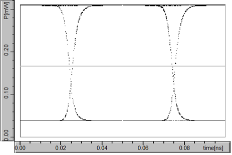
Oscilloscope plots of the MZI output are shown for the following different cases: 1. Electrode is phase velocity matched to optical waveguide (nelec = nopt = 3.5) and terminated by matched resistance (Zelec = Zterm=50 Ohm)
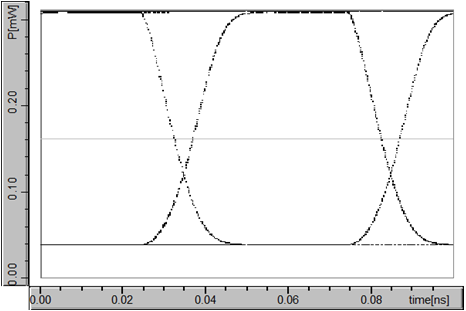
2. Electrode and optical waveguide are phase velocity mismatched (nelec = 5, nopt = 3.5). This results in a longer rise time in modulated optical signal.
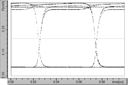
3. Impedances of electrode and termination are mismatched (Zelec = 50 Ohm, Zterm = 55 Ohm). This causes reflections in the electrical signal at end of electrode which alters the waveform shape of the modulated optical signal.
|
 © 2023 Photon Design copyright all rights reserved |

 |